Hardware Overview of the smfBox
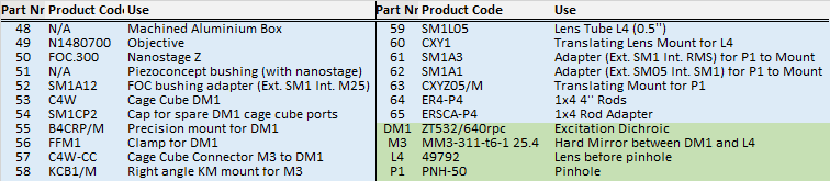
- Excitation Pathway
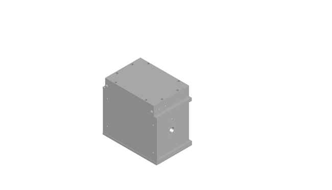
- Microscope Body
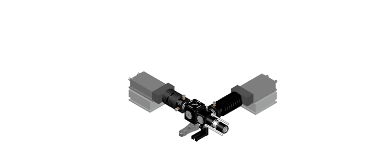
- Emission Pathway
- Wavelength Dependent Optics
The smfBox can be divided into three sections:
Also on this page is a run down of the wavelength dependent optics
Excitation Pathway
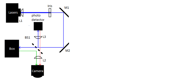
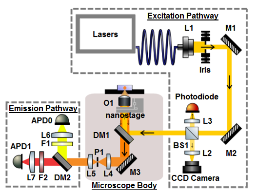
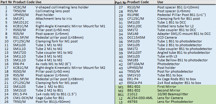
The excitation pathway is built from a precision iris, two kinematically mounted mirrors, a beam splitter, a photodetector, and a ccd camera. Optomechanical components are mounted on non-height adjustable posts with cage-rods between them to ensure robustness of alignment. After being trimmed by the iris, the mirrors M1 and M2 give complete axial stabilisation of the beam before entering the box. The beam splitter BS1 on the first pass (blue line) reflects 10% of light through a lens (L3) onto a nanosecond rise time photodetector for calibration of laser alternation and power, whilst permitting the other 90% through to the cube. Backscattered light from the sample (green beam) is reflected off the back of the beam splitter, through a lens (L2) onto a CCD camera which is used for focusing the objective. One potential problem can arise from reflections off the photodetector passing through the beam splitter onto the CCD (dashed red line), this is averted by mounting the photodetector at a slight tilt.
The photodetector proved a useful diagnostic tool during construction of the scope for calibrating ALEX period and laserpowers, however with the APD's set up this can now be done using the ALEX tab in the acquisition labview software. The photodector is not at all required for normal acquisition of data, so whilst we recommend that you include it due to it's use as a diagnostic, it is worth noting that it is not entirely necessary.
Microscope Body
Emission Pathway
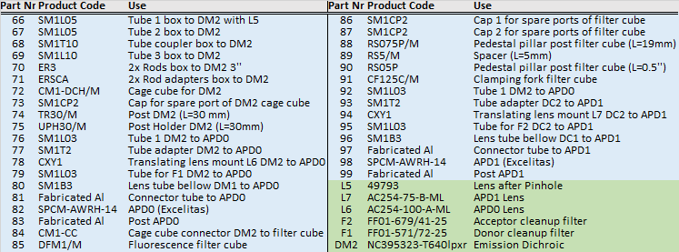
Wavelength Dependent Components
These are the wavelength dependent components used in the original smfBox, if you would prefer to excite with / detect a different set of wavelengths then that should be possible, but you will need to change these. Note that whilst the 515 laser cannot excite common green fluorophores as efficiently as a 532, it can be more easily digitally modulated without the use of an AOM, and can also excite fluorophores in the 488 range allowing for a wide choice of labelling.| Part Name | Company | Product code | Quantity | Part Nr |
|---|---|---|---|---|
| Omicron LightHUB®-2 with 515nm 80mW, and 638nm 100mW | Omicron | LightHUB-2 | 1 | Laser |
| Excitation Dichroic | Chroma | ZT532/640rpc | 1 | DM1 |
| Emission Dichroic | Chroma | NC395323 - T640lpxr | 1 | DM2 |
| Donor Emission Filter | Semrock | FF01-571/72-25 | 1 | F1 |
| Acceptor Emission Filter | Semrock | FF01-679/41-25 | 1 | F2 |
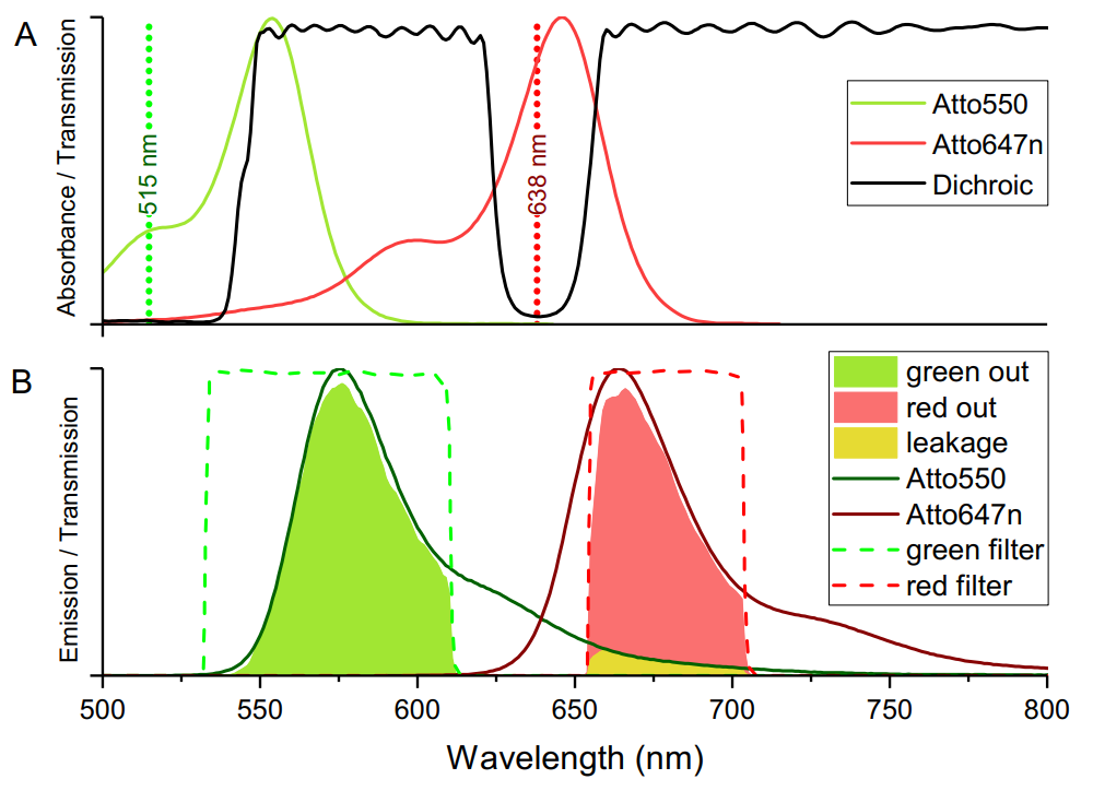
On casual inspection of the above graph it may appear that greater signal from the donor could be acquired with a longer wavelength bandpass filter. It is worth noting that whilst this is true, it would also permit emission of the raman scatter from the 515 laser, so the bandpass filter used was selected specifically to remove this scatter and lower background.